DIY Fun: Extremly cheap solar power monitoring with ESP32 and InfluxDB2

I have at my home's window a small experimental solar setup, consisting in one (sometimes two) 30W 18V solar panel, a rubbish MPPT controller, and a 12V 10A lead-acid battery. Once you set it up, you want to have metrics and stuff, right? So my next-thing-to-do was to find a way to collect power data and push it somewhere - preferably in my local Grafana + InfluxDB2 setup I use for all kind of time series data.
The first step forward was to search a MPPT controller which knows WiFi and reads power, and then implement some sort of integration with it in order to bring the data where I want - they should exist, and be affordable, right? Nope. Upon research, I could could barely find some WiFi-capable ones, and those which were, were more than 100$ - not worth it. So... better build one by myself.
In order to achieve that, I would clearly need an ESP32 to read the power data from some kind of module capable of reading current power and transport it via WiFi. So, in my setup, I finally decided on just two elements:
- • an ESP32 C3 SuperMini - which is an loT mini development board based on the Espressif ESP32-C3 WiFi/Bluetooth dual-mode chip. It has 11 digital pins, and 4 analog pins which can be used as ADC pins (Analog To Digital Conversion)
- • an ACS712 current sensor module. It is capable of reading the amperage in a circuit and, given the fact that by nature a solar panel is consistent in its voltage even at low power, we could compute the estimated power fairly consistent.
On AliExpress a C3 SuperMini usually costs 2-3 euros (I actually got mine at 1.8 euros), and the ACS712 normally comes in pack of 5 or 10 - for a pack of 5 pieces I paid 4.5 euros. So the cost per units for this individual setup is <3 euros!
A catch about ACS712
The ACS712 sensors come in 3 variants: for maximum currents of 5A, 20A and 30A. It has 2 connections for the circuit for which the power has to be monitored, and 3 pins: VCC (power supply at 5V), ground, and output. The sensor outputs a voltage centered around 2.5V at 0A on the monitored circuit, and 5V for its maximum amperage, based on its rating (for example, using the ACS712 20A variant, the output will be 2.5V at 0A, and 5V at 20A),
However, there's an important catch: the analog pins on the C3 SuperMini can only read up until 3.3V! So the ACS712 variant has to be picked not just based on the expected maximum current produced by the solar panels, but in such way that the maximum output of the sensor would not go above 3.3V.
In my setup I accounted for 2 x 18V 30W solar panels, connected in parallel, so roughly 3.34A at maximum. If I were to use the ACS712 5A variant which has a sensitivity of 185 mV/A, at 3.34A the output pin's voltage would be approximately 3.12V - thus below the 3.3V limit of my ESP32 C3.
In order to maintain the output below 3.3V, each ACS712 variant should support at most a current of:
- • ACS712-05B (5A version): maximum current 4.32A
- • ACS712-20A (20A version): maximum current 8.0A
- • ACS712-30A (30A version): maximum current is 12.12A
Downsides of ACS712
It is important to also note some downsides of this sensor:
- • is susceptible to noise, which can result in fluctuating readings. In practice I saw some fluctuations, but fortunately they are minor
- • requires calibration - in my case the zero-current voltage was not what I expected, and I needed to adjust
- • the zero-current voltage can also drift due to temperature changes, potentially requiring another calibration
- • the resolution may not be sufficient for accurately measuring very small currents, which is common during low-light conditions or idle periods for solar panels. For example, the 5A variant has a sensitivity of 185 mV/A, which might not detect small current variations accurately. Because of this combined with the fluctuations, in my setup I opted to just discard low-power readings.
Connecting the wires
I connected the positive wire coming from the solar panels to the right circuit connection of the ACS712 (as you position it face up with the pins at the bottom and the circuit connections at the top), and the MPPT solar positive to the left circuit connection of the ACS712. Then, I connected the ACS712 VCC pin to the C3's 5V pin, the ground to ground, and the OUT pin to C3's pin GPIO1/A1
Programming the ESP32
I build the following sketch in Arduino IDE, which:
- • connects to WiFi
- • reads the sensor data every minute while trying to maintain the same second for the reading, using 10 samples and averaging the results
- • calculates the power based on the reading and the known voltage
- • pushes the reading to my InfluxDB2 time-series database
- • uses ESP32's light sleep mode between readings to optimize the overall power consumption.
#include <WiFi.h>
#include <HTTPClient.h>
#include <esp_sleep.h>

// Pin Definitions
const int ACS712_PIN = 1;         // ADC pin connected to ACS712 OUT pin
const float ACS712_SENSITIVITY = 185.0; // Sensitivity in mV/A for the 5A version
const float ADC_VOLTAGE_REF = 3.3; // ESP32 ADC reference voltage in volts
const int ADC_RESOLUTION = 4095;   // ESP32 ADC resolution (12-bit ADC)
const float ZERO_CURRENT_VOLTAGE = 2.93; // Output voltage at 0A in volts
const float PANEL_VOLTAGE = 17.9;  // Nominal voltage of the solar panels (assumed constant)
const long MEASUREMENT_INTERVAL = 60000; // 1-minute interval (in milliseconds)
const bool ENABLE_LIGHT_SLEEP = true; // Use light sleep to reduce the power consumption of the ESP32. Disable when calibrating/testing

// Variables
float current = 0.0;  // Current in Amperes
float power = 0.0;    // Power in Watts

// InfluxDB2
const char* influxDB_URL = "http://192.168.x.x:8086";
const char* org = "myinfluxorg";
const char* bucket = "solar";
const char* token = "yourtoken";

const char* ssid = "MyWiFiSSID";
const char* password = "MyWiFiPassword";

uint32_t chipid;
const char* chipModel = "ESP32 C3 SuperMini";

WiFiClient wifiClient;

// prototypes
int readADC(int pin, int samples);
float calibrateZeroCurrent(int pin, int samples);
void sendToInfluxDB(float power);
void connectToWiFi();

void setup() {
  Serial.begin(115200); // Start serial communication for debugging
  delay(1000); // Allow time for Serial Monitor to open

  Serial.println("Initializing...");

  chipid =  ESP.getEfuseMac();
  Serial.println("Chip ID: " + String(chipid));

  WiFi.mode(WIFI_STA);
  Serial.println("WiFi mode set");

  connectToWiFi();

  analogReadResolution(12);        // Configure ADC resolution for ESP32
  analogSetAttenuation(ADC_11db);  // Adjust ADC range to support 0–3.3V readings
  delay(1000);                     // Wait for the system to stabilize
  Serial.println("Pin modes configured");

  Serial.println("Solar Panel Monitoring Started...");

  /*
  // Calibrate zero-current voltage with averaging
  ZERO_CURRENT_VOLTAGE = calibrateZeroCurrent(ACS712_PIN, 20); // Average 20 readings
  Serial.print("Calibrated ZERO_CURRENT_VOLTAGE: ");
  Serial.println(ZERO_CURRENT_VOLTAGE, 3);
  */
}

void loop() {
  long startTime = millis(); // Record the start time of this loop iteration

  // Check WiFi
  if (WiFi.status() != WL_CONNECTED) {  // Check if WiFi is still connected
    Serial.println("WiFi lost. Reconnecting...");
    connectToWiFi();  // Reconnect if connection is lost
  }

  // Perform the measurements
  int rawADC = readADC(ACS712_PIN, 10); // Average of 10 readings
  float voltage = (rawADC * ADC_VOLTAGE_REF) / ADC_RESOLUTION;
  float current = (voltage - ZERO_CURRENT_VOLTAGE) / (ACS712_SENSITIVITY / 1000.0);

  // Ignore small currents/power
  if (current < 0.01) current = 0.0; // Treat currents below 10mA as zero
  float power = current * PANEL_VOLTAGE;
  if (power < 0.5) power = 0.0; // Treat power below threshold as zero

  // Print current and power to the Serial Monitor
  Serial.print("Current: ");
  Serial.print(current, 3); // Print current with 3 decimal places
  Serial.print(" A, Power: ");
  Serial.print(power, 2);   // Print power with 2 decimal places
  Serial.print(" W, Voltage: ");
  Serial.print(voltage, 2);   // Print power with 2 decimal places
  Serial.println(" V");

  // Send data to InfluxDB
  sendToInfluxDB(power);

  //delay(5000); // Delay between readings

  // Calculate the time taken for operations
  long operationDuration = millis() - startTime;

  // Calculate sleep duration
  long sleepDuration = MEASUREMENT_INTERVAL - operationDuration;

  // If time remains in the interval, enter light sleep
  if (sleepDuration > 0) {
    if(ENABLE_LIGHT_SLEEP == true){
      Serial.print("Entering light sleep for ");
      Serial.print(sleepDuration / 1000.0);
      Serial.println(" seconds.");

      esp_sleep_enable_timer_wakeup(sleepDuration * 1000); // Convert to microseconds
      esp_light_sleep_start();

      // Wake up and continue
      Serial.println("Woke up from light sleep.");
    }
    else{
      delay(sleepDuration * 1000);
    }
  }
}

// Reads and averages multiple ADC readings
int readADC(int pin, int samples) {
  long sum = 0;
  for (int i = 0; i < samples; i++) {
    sum += analogRead(pin);
  }
  return sum / samples; // Return the average value
}

// Calibrates the zero-current voltage by averaging multiple readings
float calibrateZeroCurrent(int pin, int samples) {
  long sum = 0;
  for (int i = 0; i < samples; i++) {
    sum += analogRead(pin);
    delay(10); // Small delay for stability
  }
  int avgADC = sum / samples;
  return (avgADC * ADC_VOLTAGE_REF) / ADC_RESOLUTION;
}

// Sends power data to InfluxDB
void sendToInfluxDB(float power) {
  if (WiFi.status() != WL_CONNECTED) {
    Serial.println("Wi-Fi not connected!");
    return;
  }

  HTTPClient http;
  String url = String(influxDB_URL) + "/api/v2/write?org=" + org + "&bucket=" + bucket + "&precision=s";

  http.begin(url.c_str());
  http.addHeader("Content-Type", "text/plain");
  http.addHeader("Authorization", String("Token ") + token);

  // Prepare line protocol data
  String data = "solar_power value=" + String(power, 2);

  int httpResponseCode = http.POST(data);
  if (httpResponseCode > 0) {
    //Serial.print("HTTP Response Code: ");
    //Serial.println(httpResponseCode);
    if (httpResponseCode != 204) {
      Serial.println("Failed to write data to InfluxDB!");
      Serial.println(http.getString());
    }
  } else {
    Serial.print("HTTP Error: ");
    Serial.println(http.errorToString(httpResponseCode).c_str());
  }

  http.end();
}

// Function to connect to WiFi with retry logic
void connectToWiFi() {
  int maxRetries = 20;   // Maximum number of connection attempts
  int attemptCount = 0;  // Attempt counter

  if (WiFi.status() != WL_CONNECTED) {
    Serial.print("Connecting to WiFi...");
    //WiFi.forceSleepWake();
    delay(1);
    WiFi.mode(WIFI_STA);
    WiFi.begin(ssid, password);  // Start WiFi connection

    // Retry loop for connecting to WiFi
    while (WiFi.status() != WL_CONNECTED && attemptCount < maxRetries) {
      delay(500);
      Serial.print(".");
      //Serial.print(" Status: ");
      //Serial.println(WiFi.status()); // Prints the WiFi status code
      attemptCount++;
    }

    // Check connection status
    if (WiFi.status() == WL_CONNECTED) {
      Serial.println("\nWiFi connected!");
      Serial.print("IP address: ");
      Serial.println(WiFi.localIP());  // Print the device's IP address
    } else {
      Serial.print(" Status: ");
      Serial.println(WiFi.status());  // Prints the WiFi status code
      Serial.println("\nFailed to connect to WiFi.");
    }
  }
}
For the first time, you need to disconnect the solar panels and watch for the voltage which the ESP32 displays in the Serial Console, disregarding the power readings. Then, treat the voltage as the zero-current voltage, update the ZERO_CURRENT_VOLTAGE const, recompile and re-upload. In my case, although I expected to have a 2.5V zero-current voltage, it actually was ~2.93V.
First run
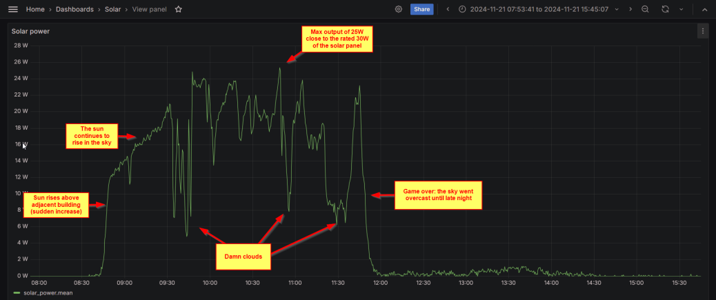
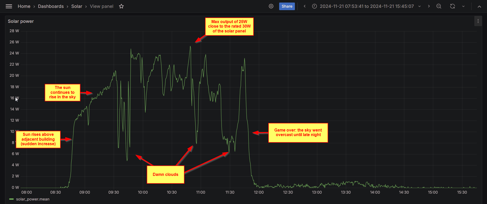
Once the setup was live, I wanted to see it in action and draw some conclusions. This is the first day:

Overall, although I expected to have only a rough estimate, it seems more accurate in reading than I expected!